February 2026
- paddleriver
- Mar 1
- 16 min read
It feels like it has been a quiet month but, in reflection, lots has happened.
The weather was fantastic for the first two weeks of the month. Who needs to go south when the temperature is in the upper teens for days in a row? The snow was almost gone by the first week of February. It was so nice that the Christmas lights were taken down on February 2. Winter got it’s revenge over the second half of the month, with temperatures dipping to -30 at night, and 20cm of snow in one day, followed by another 20cm a week later.
Stitch’s physio has evolved. There are exercises to do at home to help build strength and straighten his “lazy” foot. He started doing water tread mill, but after several sessions, it wasn't clear how it benefited him. Discussion with the vet revised the plan, since it seems that his posture is good for the first half of the day, but deteriorates as he gets tired/sore. The risk is that he favours the leg as it gets sore, reinforcing the bad habits and posture. He was put on Metacam for a week, for pain and inflammation control, and saw an immediate improvement in his behavior and posture. Based on this, the vet has suggested he begin laser therapy, to help manage stiffness and pain. He had his first session mid month, and another list past week, and it seems to help. He is getting back to his old self, running and jumping all the time. Good to see and the hope is that this will help speed up muscle regeneration.
We were watching lots of Olympics on TV. One of the advantages of being retired is that you can watch live regardless of the time differential. It feels strange now that it has ended and “normal” TV has returned.
Railway
Track and power is now complete in Oulton. A layout clean up was done the first week of February to put away all the tools and free up space. It proved to be a bit premature. A week of operating different combinations of locomotives and cars through the Oulton trackwork has found a surprising/disappointing number of repairs. Most were turnouts, and most of these had already been repaired at least once before. After several hours work, things seemed to be running better. A "final" pass was made with the H1a Hudson, a 4-6-4 steam locomotive, whose long wheelbase makes it especially sensitive to track issues. It ran beautifully through all the completed repairs. As it passed through the last turnout, one that hadn't needed repairs, it gave a huge lurch that would have thrown the scale crew out of the cab. Nothing was found after an hour of troubleshooting. Next morning, a careful second examination found a number of problems, including wide gauge through the frog, and a track kink leading into the departure leg. The fix involved relaying about 30 cm of track, resoldering the frog ties, and respiking about 50 cm of track. A small bump is still noticeable as the locomotive passes through the turnout, but it would only jostle that scale crew, rather than throw them out of the cab.
Continuing to test track, other locomotives and cars are being pulled out of storage. It seems each new locomotive or car tested finds another problem. It doesn't seem like there has been a session that hasn’t needed adjustment of some track component. Annoying but better to find it now while it is still open and easy to fix.
With clean, and empty space available, a number of storage boxes, containing previously built structures, were unloaded. The boxes held a mixture of buildings, some inherited from my Dad, while others were ones I had previously built. The town of Oulton was designed around its grain elevators, so it was a priority to get these out to see how they would fit. The elevators fit but it was tight, potentially restricting construction of a road behind them. That was a concern.
The desire was to make an even larger elevator the town's focal point. The larger elevator, bought at last year's Edmonton train show, was a 1948 standard enlarged design, and would be much larger than those previously built. Aware of its size, the kit's measurements had been used to set the track position. Given the importance of this desired scene, it was felt prudent to build this kit and get spacing sorted out before doing any more benchwork construction. If needed, it would still be possible to add an extension to the front of the existing bench work, or worse case, relocate the bigger elevator to the unnamed town.
Speaking of the unnamed town, potential names have been explored. See if any of these options strike a chord:
a) Riley. He's our oldest dog. I like the sound of the name. It is actually a real town in Alberta so it might be confusing.
b) Ember. Another of our dogs. It also "sounds" right. There is an Amber Valley near Athabasca but no Ember.
c)There has been a number of friends from high school and university that had names that seemed to "fit" the Alberta small town theme. Perhaps not surprising, as last names were commonly used in some form for many town names. Possibilities include Wolgar, McKenzie, Elvidge, Otholf, Stocker, Abernethy and Sullivan
d) Davis or perhaps Davies. Davis is the last name our Nicholas' fiancé.
e) Alex. A shortened version of my father's middle name. There is a real Alix in Alberta but no Alex.
f) Paddle River. There is a Paddle Prairie, and an actual river named Paddle, but no town. It was planned to model a river named Paddle River. Given the use of this name for many things, perhaps it would be fitting for it to find a more concrete presence.
g) Write in your own suggestions.
Photo 1 - Oulton grain elevators from the west
Photo 2 - Oulton grain elevators from the east
Photo 3 - The bigger grain elevator kit


Monashee Laser Engineering Alberta Wheat Pool Elevator
This kit was bought a year ago at the Edmonton train show. The vendor is Calgary based, and has an extensive line of laser cut wood kits of Canadian railway structures.
The kit is based on a standard 1948 design created by the Alberta Wheat Pool. Post war, grain production increased dramatically, and existing elevators were proving too small. New designs, like this 1948 enhanced design, were soon being built all across the province to handle the new bounty. Three of the five elevators in Barrhead, which in many ways has inspired this current layout, had three of these.
Opening the box is a little intimidating. There is a lot of wood and not many instructions. Most of the kit consists of sheets of wood which have be laser cut to create parts, only needing minor cutting to free the part from the sheet. It took a bit to realize that most of the parts/sheets have really small labels, mainly located on the mating tabs, making it easier to figure things out.
Construction started with the approach ramps. The instructions simply show the finished ramps from above, giving relatively little construction info. It took a few minutes to identify the appropriate pieces, and a few more minutes to sort out the labelling system. Test fitting various parts proved essential to figure out the best way to put things together. Fit was tight and secure. Fifteen minutes later and the approach ramps were complete, ready for paint.
The instructions suggest painting and staining all the wood pieces before assembly. Sepia coloured Hunterline stain was used for all the unpainted wood. The instructions recommended that the painted wood be sprayed with a gray automotive primer, so this was duly applied. An appropriate teal coloured paint, typical of Alberta Wheat Pool elevators, was purchased from Monashee when the kit was bought. It is an acrylic paint, akin to craft paint, and very thick. Given the paint's thickness, initial thought was to brush paint the pieces, but there is a lot of wood, and the instruction don't recommend it. They instead suggest the paint be thinned, and then airbrushed, which that became the path forward. The paint thinned well with water, and had good coverage, but it proved difficult to cover the grey primer. In hindsight, it would have been much better to have used a white primer, as it took 6 or 7 coats of teal to get decent coverage.
The elevator walls are made by laminating sheets of exterior clapboard onto 3/16" hardboard interior walls. There are a lot of pieces to join, with each needing to be weighted down to ensure a good bond, meaning it took several days to get everything glued together. The taller exterior walls are actually multiple sheets of wood, taped together on the backside, in order to get the necessary height. The tape held the sheets together quite tightly, so it was decided to glue each taped sheet directly to the backing. In hindsight, the joints between sheets should have first been glued together before the sheets were then glued to the backing. The taped joints looked fine after painting but become quite noticeable after being glued to the backing. Some careful sanding and scraping minimized but didn't eliminate the joint lines.
A small storage shed was the first building constructed. The four walls proved a tight fit. The roof is shingled using self adhesive shingle strips, a simple and easy solution. The instructions require a starter strip be placed along the bottom edge, but don't give any hint where to find them. It took some time to locate it, finally realizing it was a part of the shingle sheet that had been mistaken as scrap. The door casing and the eave trim is laser cut from wood sheet with a self adhesive backing, making it very easy to install. The wall's corner trim proved equally easy to install. The walls have cut outs at each corner, allowing a scale 6x6 section to be painted and glued into the cut out. After a couple hours, mostly to let the glue set, the shed was complete.
Photo 1 - Lots of parts
Photo 2 - Approach ramps ready for paint
Photo 3 - Primer/sealer complete. There was a lot of wood to paint
Photo 4 - Prepainted kit parts, ready to assemble
Photo 5 - Storage shed components ready to assemble
Photo 6 - Finished shed. Might need to touch up that roof.


Next was the office building. It's construction was very similar to the storage shed, with a couple new tasks. The interior stairs consisted of laser cut risers and laser cut treads. Just separate the appropriate parts from their backing sheet and glue them together. No measuring and no fuss. The door was a two part sandwich, with the front panel cutouts already done by laser. Window construction wasn't immediately obvious, and it took a bit to figure the sequence out. Each window consists of two self adhesive, laser cut casings that need to be separated from the backing sheet. Laser cut acetate window "glass" is then trimmed with scissors, then applied to be back of the casing. The upper casing section is pushed into place from behind, attaching to the back of the window trim piece. The second casing section is then pushed up against the bottom of the first casing. The process is a little fiddly but the result looks convincing. (see photo 2 below)
A couple challenges were encountered while constructing the exterior stairs. The instructions don't give any dimensions for the stair posts, so it wasn't clear how high they were supposed to be. It was eventually realized that the kit provided scale drawings, allowing dimensions to be obtained by measurement. With that figured out, the handrails were quickly completed. A test fit of the exterior stairway to the office found that the included stair base plate mounting lug was oversized and would not fit into the office base plate. Some trimming was needed before the stairs would slot into place, only to discover that the handrail posts fouled the side of the building. Relocating one post solved the problem, allowing the stairs to sit flush.
Photo 1 - Office stairs, never to be seen again
Photo 2 - Installing windows and door. Components are shown on the piece above the wall
Photo 3 - Joining the walls needed a lot of clamps
Photos 4&5 - Office essentially finished
Photo 6 - Office stairs in construction


Two structures complete but still a lot of wood left in the box. It wasn't immediately apparent how all those pieces fit together so a dry fit of the interior walls was undertaken to figure things out. A pencil was then used to number each piece, then matched up with the equivalent exterior siding piece. The inner and outer walls could now be confidently laminated together.

Construction moved on to the cleaning shed ramp and supports (See photo 1 below). In an apparent trend, it took some time to sort out what parts were needed, and several dry fits were required to figure out how everything fit together.
Next up were the cleaning shed walls. The walls have been laser etched to represent the horizontal wood siding and to show the location of the vertical columns, lintels and beams, and studs. It was eventually realized that each of the verticals needed to be individually cut, from lengths of stripwood, and glued to the respective wall. It proved a slow process that took several days to complete. (Photo 3 below)
It was now finally time to assemble the actual elevator. The base is composed of two laser cut base plates, but it wasn't clear how they stacked together. It also wasn't clear what parts were used to build the floor joints, or how they stacked together. Some time spent dry fitting things together sorted things out, realizing the base plates needed to be attached opposite to what was initially thought. Easy to rearrange pieces if nothing has been glued together.
It was here I encountered the first real problem. Two as it turned out. The first was that the first floor section didn't rest on the floor support joists. It was necessary to add some scrap wood spacers to bring the supports up to the correct height. (Photo 4 below) This should have forced a pause to revaluate construction, and failure to do so would come back to cause further problems. The next problem occured when it wasn't possible to install the interior walls without considerable force. Stepping back, it was realized that the walls were about 2mm too long on both sides. A sharp knife was used to trim the walls back until things fit properly. (see Photo 5 below)
Elevator wall assembly began with the cleaning bay. There was no way it would be possible to manage all four walls, with glue on the edges, then add clamps, before the glue dried or covered things it wasn't supposed to. It was found to be easiest to install a wall, clamp it in place, then let the glue dry. Then add the next wall, clamp it, and let the glue dry. Repeat until all four walls are in place.
Unfortunately, it was about now that disaster struck. Note in photo 7 below how many clamps are in place, and how close the elevator is to the edge of the desk. As the last clamp was added to hold the last wall in place, the elevator over balanced and crashed to the floor. Surprisingly, the joints held, but it must have landed on the top as one of the peaked ends cracked. Straightening it out caused it to break and separate. Despite best efforts, it was not possible to get a tight fit and a noticeable gap was left. (see Photo 8 below) Initial repairs focused on using a water soluble filler, filling the gap but allowing excess to be wiped away. It sort of worked, but was still visible even under paint. (Photo 9 below). A piece of 2x4 stripwood was tried, cut to length and sanded to approximate the correct clapboard shape. It was glued into position and then further shaped by careful sanding. It was still noticeable after painting but was an improvement over the initial repair.
Photo 1 - Underside of the out drive shed floor
Photo 2 - Building a wall section sandwich. Hardboard interior wall on the right. Clapboard siding exterior wall on the left.
Photo 3 - Stud walls complete.
Photo 4 - Spacers needed to seat the floor plate properly
Photo 5 - Walls (at the top of the picture) are 2mm longer, on both ends, than the corresponding floor plate (at the bottom of the picture)
Photos 6 - Installing the outside walls.
Photo 7 - Three walls and a lot of clamps
Photo 8 - Not sure how to fix that.
Photo 9 - Not a perfect repair but better than expected.
Photo 10 - Trying an alternate repair
Photo 11 - Better, I think?
Photo 12 - Let there be light


The last major section to add was the exterior cleaning shed wall. This was when earlier decisions came home to roost. Simply put, the wall could not be put into place. After gently moving various pieces of interior framing, the wall slotted into place but would not close tightly to the existing walls. It became apparent that the previously installed floor joists, the ones needing spacers, extended too far out and were fouling the wall. A pair of side cutters were used to crudely remove 3mm - 4mm from each joist before the cleaning shed wall would fit into position. Even then, it needed use of a lot of clamps, with a lot of force, to keep things in place until the glue set.
A pair of LEDs were added to the cleaning shed before closing it up. Photo 12 above shows how it looks. The interior framing is very visible from the open loading doors, and looks pretty good.
Photo 1 - Adding the cleaning shed wall took some effort.
Photo 2 - Cleaning shed wall in place. Adding corner trim pieces.
Photo 3 - Cleaning shed rood complete.


A trail fit on the layout shows that the elevator does fit but there is virtually no space behind it. It may need a small benchwork extension to allow a road. It certainly dominates the older, much smaller elevators.

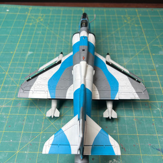
Magic Factory 1/48 Skyhawk
With paint complete, it was time to add the Above and Below Graphics decals. They were thin, released quickly in warm water, and mostly went on without problem. The lone exception was the starboard side "beware jet blast" decal, which came off the backing in paper in less than 2 seconds, then immediately folded up into a ball. If was mostly straightened out and placed into position but it's noticeable if you look closely.
At this point a panel line wash would normally be applied but the real plane is kept spotless. Closeup photos barely show panels let alone panel lines. It was decided to apply a light gray wash, but to avoid the rivets. A thinner than normal Payne's gray wash was made using oil paints, providing just the right amount of highlight.
With paint and decals complete, it was time to attach the detail bits. The leading edge flaps proved a pain to install, but look really nice once done. Landing gear was next, slotting in positively.
With most of the details attached, it was time for a final cleat coat. As previously noted, the real plane is very clean and actually shiny. A semi gloss flat was used, as a gloss cost never looks right on anything but an airliner. The builds "all thumbs moment" then resulted in the nose cone getting banged against the spray booth while applying the clear coat, knocking it loose. The repair needed a lot of care, as the break passed through the large nose ID decal, and there were no spares. Thankfully it went back on with no fuss.
Final assembly consisted of the drop tanks, the horizontal stabilizers, the gear bay doors, and the refuelling probe. Landing gear doors are normally difficult to install, but these had very well engineering attachment points and went on without issue.
Photo 1 - Decals complete.
Photo 2 - Panel liner complete on topside
Photo 3 - Panel liner complete on underside
Photo 4 - Oops
Photo 5 - Adding details
Photo 6 - Done!


And with that, the Skyhawk was complete. This was a really nice kit. It went together well, without need of much filler or fettling. Well, other than the multi part nose cone, which was clearly intended to be displayed open, Closing it up took a fair bit of work. The splinter paint scheme took a lot of masking, and would be approachec differently if another was built. White is difficult to apply, and doesn't cover other colours well. The masking had some bleed through and clean up needed white to be applied over other colours. The white wouldn't cover up the base colour and ended up obscuring some of the fine rivet detail. It would have needed more masking but it would have been better to clean up the bleed through using the colours.
Here are the final pictures.
First, the plane from all angles.


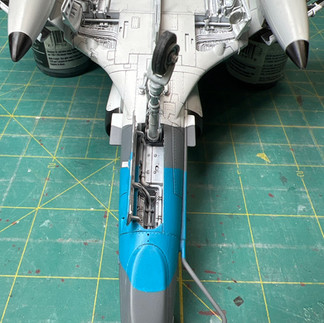
The underside


The canopy and cockpit


The modified N model jet pipe


Some pictures using the hanger backdrop


And last, a picture of the finished plane, crammed into the display shelf

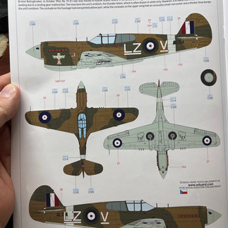
Eduard 1/48 Royal Boxing P-40E Warhawk
Next kit(s) on the bench will be the Royal boxing of the Eduard 1/48 P-40E Warhawk that the kids got me as a Father’s Day present last year. An Eduard Royal boxing is the premier issue of a model, with two kits in the box, with extra detail parts, lots of photoetch, and canopy masks.
In Commonwealth use, the P-40E was known as a Kittyhawk Mk.1 or Mk.1a. The P-40 had a mixed reputation, often considered to be a less than successful plane. It had a number of shortcomings but perhaps the biggest was the lack of a supercharger on the Allison engine. This severely limited performance at altitude, a critical factor over Europe, where much of the aerial combat took place at higher altitude. It was much less a factor in the Pacific and Africa, where combat was at lower elevations. In the hands of skilled pilots, P-40’s could hold their own at lower altitudes, and were critical in the early days of defending China and North Africa, where they were often the only planes available.
The RCAF had several squadrons of Kittyhawks, Mks I through IV, that served in Western Canada and Alaska. They were also flown by Canadians serving in the RAF, notably in North Africa. Sufficient reasons to include two in my collection.
The kit includes markings for eight different aircraft, with several Commonwealth planes, including one in RCAF markings. It was initially planned to build the RCAF version, but after searching through the decals stash and checking references, it was instead decided to build a different plane, Vancouver IX. The main reason this plane was chosen is the desire to build a version with an unofficial maple leaf emblem on the nose.
The other plane has to be one of the Kittyhawk flown by James “Stocky” Edward’s in North Africa. He joined the RCAF at 19, and was sent to North Africa as a fighter pilot, where he would eventually claim 13 1/2 aerial victories, winning a DFC and bar and a DFM. He went on to fly Spitfires in Italy, rising in rank to Commander 127 Wing RCAF, in command of 4 RCAF Squadrons, at the tender age 23! If interested, you can read more about him here https://en.wikipedia.org/wiki/James_Francis_Edwards?wprov=sfti1#World_War_II
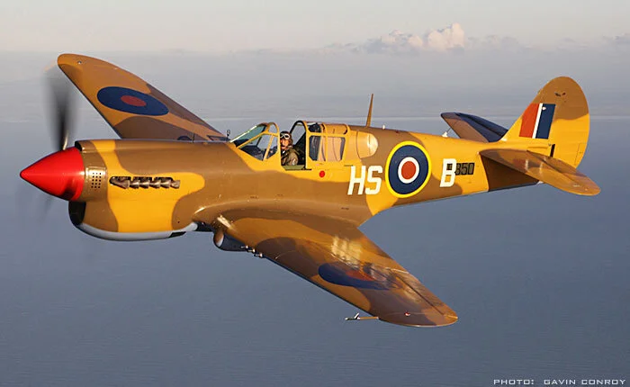
There has always been a desire to do a plane in North Africa campaign markings, with the two tone brown paint. The only thing missing from either of the two planes he used in North Africa was the characteristic shark’s mouth used by the more famous RAF 112 Squadron. His second Kittyhawk has been recreated by Vintage Wings of Canada, who painted their Kittyhawk up to represent his plane. They also have a couple of really good articles about this plane and his service career.
It was only later that it was realized that the Vintage Wings plane is marked as HS-B, Edward's plane while he was with 260 squadron. The decals I have on hand are for his earlier plane, FZ-R, when he served with 94 squadron. Still some time to sort out which of his planes to model.
Photo 1 - Kit markings for RCAF 111 Squadron with the Thunderbird totem emblem
Photo 2 - Selected markings for Vancouver IX
Photo 3 - Vintage Wings Kittyhawk HS-B


Work has started with parts clean up and painting prep, but not enough progress to justify any pictures.
Not sure if there will be a March or April blog. Marie and I are off to the eastern Mediterranean and will be gone for 4 weeks. Might not be enough modelling to create a blog entry.
And that's it for another month. Stay warm and safe


Comments